High precision water metering solution provider
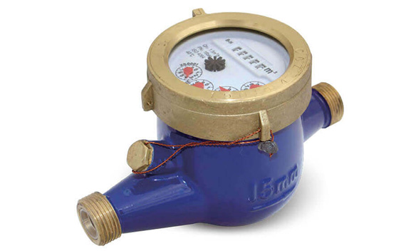
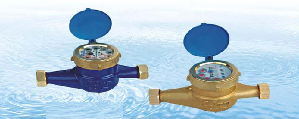
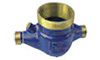
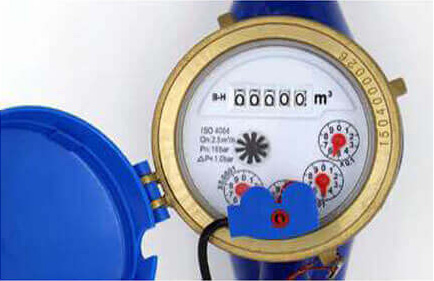
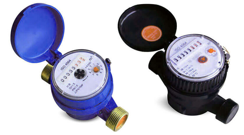
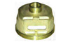
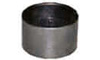
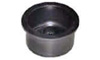
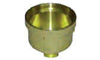
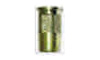
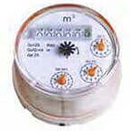
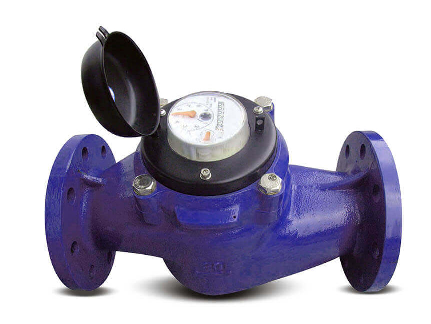
Multi-Jet Vane wheel type
Dry-dial Brass body water meters
It is a multi-jet dry type water meter for residential application in sizes 15mm-50mm for cold /hot water.
- Magnetic Drive, Lower transmission resistance.
- Magnetic shield, for external magnetic field protection.
- Sealed dry register ensures long time clear reading.
- External regulating device.
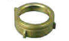
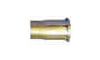
Accressories: 2pcs coupling, 2pcs coupling nuts and 2pcs washers.
Standards ComplianceTechnical data conform to international standard ISO 4064.
Working Conditions- Water temperature: O.TC ~ 40“C for cold water meter.
- 0.1°C ~ 90°C for hot water meter.
- Water pressure : S1,6Mpa (16 bar).
- Register sealed type: Dry type; Semi-dry type; Super-dry type
- Accuracy: R=80 ; 100; 125; 160.
- Size: 15~50mm.
- Cold / hot water
- Non return valve
- Reed switch option.
- Several lengths and connections availavle on request.
- Thread end type: BSP / NPT.
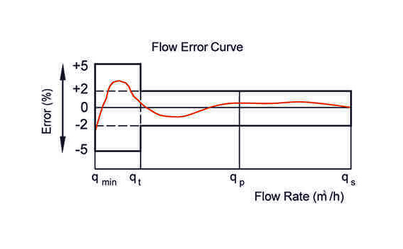
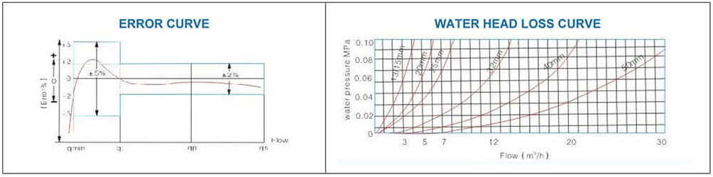
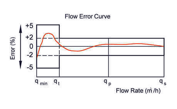
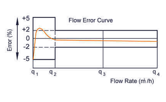
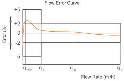
- In the lower zone from qmin inclusive up to but excluding qt is ±5%.
- In the upper zone from qt inclusive up to and including qs is ±2%; ±3% for hot water meter
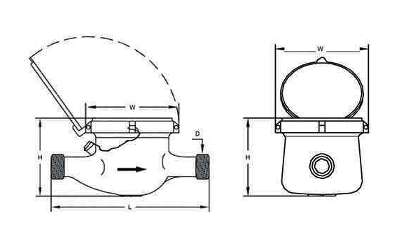
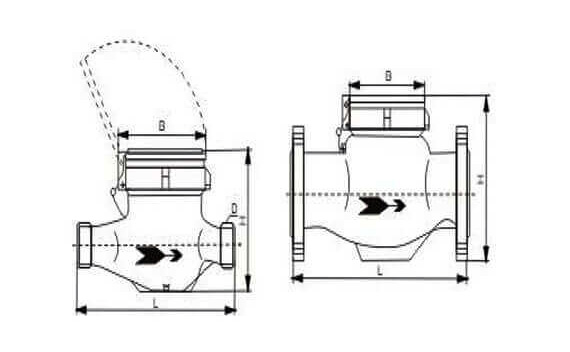
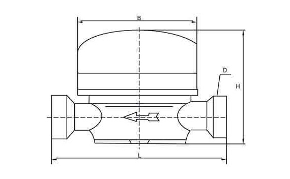
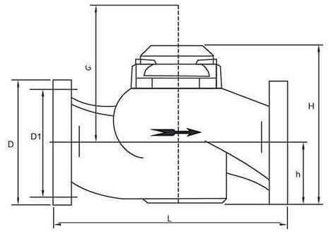
Overall Dimension And Weight
| DN (mm) | 15 | 20 | 25 | 32 | 40 | 50 | 50 |
| Size (inch) | 1/2 “ | 3/4 “ | 1 “ | 1-1/4 “ | 1-1/2 “ | 2 “ | 2 “ |
| Length (L) | 165/190 | 190 | 260 | 260 | 300 | 300 | 280 |
| Width (W) | 99/104 | 98 | 103.5 | 103.5 | 125 | 125 | 160 |
| Height (H) | 116/21 | 117 | 124 | 124 | 162 | 162 | 187.5 |
| Connecting Thread D | G3/4B | G1B | G11/4B | G11/2B | G2B | G21/2B | Flange end |
| Weight (Kgs) | 1.65 | 1.79 | 1.85 | 2.68 | 5.25 | 7.25 |
LXSG-15e~50e
 CHARACTERISTIC
- Multiple-jet, dry magnetic drive
- Vacuum sealed counter, frost proven, keeping clear reading for long time.
- LXSG-13 counter is made of red copper box
- Antimagnetic construction
- Meter body made of either brass or cast iron
- Outside and inside adjust able meter body
- For Hot and Cold Water, remote transmission device can be added upon request.
- Water temperature 0°C - 30°C (For Cold Water Meter)
- Water temperature 0°C - 90"C (For Hot Water Meter)
- Water Pressure < 1MPa
- From the minimum flow rate Q1 (including Q1) to the lower zone of the transitional flow rate Q2 (excluding Q2): ± 5%
- From the transitional flow rate Q2 (including Q2) to the higher zone of the maximum flow rate Q2 (excluding Q4): ± 2%
- Hot Water Meter: ± 3%
 MAIN TECHNICAL DATA
| DN (mm) | Ration Q3/Q1 | Q3 Permanent flow-rate Qp (m3/h) | Q2 Transitional flow-rate qt(L/h) | Q1 Minimum flow rate qt(Uh) | Q4 Overload flow-rate qs (m3/h) | Minimum Reading Min(m3) | Maximum Reading Max(m3) |
| 80 | 50 | 31.25 | |||||
| 15 | 100 | 2.5 | 40 | 25 | 3.125 | ||
| 160 | 25 | 15.625 | |||||
| 80 | 80 | 50 | |||||
| 20 | 100 | 4 | 64 | 40 | 5 | ||
| 160 | 20 | 25 | 0.0005 | 999 99 | |||
| 80 | 126 | 78.75 | |||||
| 25 | 100 | 6.3 | 100.8 | 63 | 7.875 | ||
| 160 | 63 | 39.375 | |||||
| 80 | 126 | 78.75 | |||||
| 32 | 100 | 6.3 | 100.8 | 63 | 7.875 | ||
| 160 | 63 | 37.375 | |||||
| 80 | 320 | 200 | |||||
| 40 | 100 | 16 | 256 | 160 | 20 | ||
| 160 | 160 | 100 | |||||
| 50 | 3150 | 500 | 0.0005 | 999 999 | |||
| 50 | 100 | 25 | 1000 | 250 | 31.25 | ||
| 250 | 250 | 100 |
| Model | Size (mm) | L Length (mm) | B Width (mm) | H Height (mm) | Connecting Thread D | Weight (Kg) |
| LXSG-15E | 15 | 165 | 99 | 104 | G3/4B | 1.5 |
| LXSG-20E | 20 | 195/190 | 99 | 106 | G1B | 1.7 |
| LXSG-25E | 25 | 225/260 | 104 | 120 | G1 1/4B | 2.4 |
| LXSG-32E | 32 | 230/300 | 104 | 120 | G1 1/2B | 2.8 |
| LXSG-40E | 40 | 245/300 | 125 | 155 | G2B | 5.1 |
| LXSG-50E | 50 | 280/300 | 125 | 155 | G2 1/2B | 7.2 |
Exploded View


| DN (mm) | 15 | 20 | 25 | 32 | 40 | 50 | |
| Size (inch) | 1/2" | 3/4" | 1” | 1-1/4" | 1-1/2" | 2" | |
| Q4(l/h) | 3125 | 5000 | 7875 | 12500 | 20000 | 31250 | |
| Q3(l/h) | 2500 | 4000 | 6300 | 10000 | 16000 | 25000 | |
| R=80 | 02 (l/h) | 50 | 80 | 126 | 200 | 320 | 400 |
| 01 (l/h) | 31.25 | 50 | 78.75 | 125 | 200 | 250 | |
| R=100 | 02 (l/h) | 40 | 64 | 100.8 | 160 | 256 | 400 |
| 01 (l/h) | 25 | 40 | 63 | 100 | 160 | 250 | |
| R=125 | 02 (l/h) | 32 | 51.2 | 80.64 | 128 | 204.8 | 200 |
| 01 (l/h) | 20 | 32 | 50 5 | 80 | 128 | ||
| R=160 | 02 (l/h) | 22.5 | 40 | 63 | 100 | 160 | 400 |
| 01 (l/h) | 15.62 | 25 | 39.37 | 62.5 | 100 | 250 | |
| Max Reading (m3) | 99,999 | 99,999 | 99,999 | 99,999 | 99,999 | 99.999 | |
| Min.Reading (Liter) | 0.05 | 0.05 | 0.05 | 0.05 | 0.05 | 0.05 | |
| Max.Pressure (Bar) | 16 | 16 | 16 | 16 | 16 | 16 | |
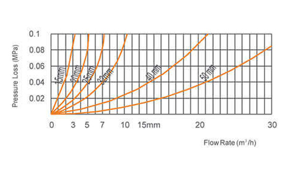
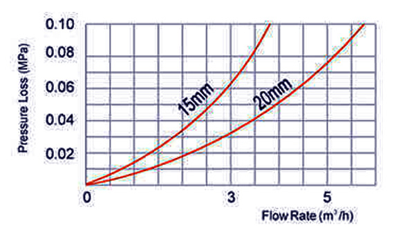
| Pressure Loss (P) | 63 | ||||||
| Max.Temperature | T=50 /90 | ||||||
| Vmax | =24V | ||||||
| Pulse Output Option | lmax=100mA | ||||||
| Pmax=2W | |||||||
| Magnet Position | Liter /Pulse |
| * 0.0001 | 1 |
| *0.001 | 10 |
| *0.01 | 100 |
| *0.1 | 1000 |
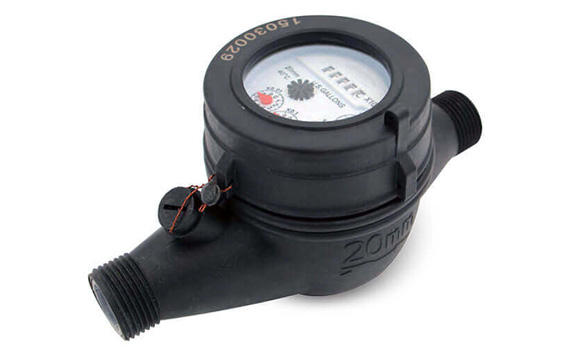
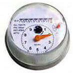
Multi-Jet Vane wheel type
Dry-dial Plastic Body Water Meters
It is a multi-jet dry type water meter for residential application in sizes 15mm-50mm for cold water.
- All the plastic raw material is 100% new material, not any second-hand material.
- High working pressure can afford PN16.
- Magnetic Drive, Lower transmission resistance.
- Magnetic shield, for external magnetic field protection.
- Sealed dry register ensures long time clear reading.
- External regulating device.
Accessories: 2pcs coupling, 2pcs coupling nuts and 2pcs washers.
Standards ComplianceTechnical data conform to international standard ISO 4064.
Optional Features- Register Sealed type: Dry type.
- Accuracy: R=80 ; 100.
- Size:15~50mm.
- Non return valve.
- Reed switch option.
- Thread end type: BSP / NPT.
- Water temperature: 0.1 °C ~ 40°C for cold water meter.
- Water pressure : < 1.6Mpa (16 bar).
- In the lower zone from qmin inclusive up to but excluding qt is ±5%.
- In the upper zone from qt inclusive up to and including qs is ±2%.
Overall Dimension And Weight
| DN (mm) | 15 | 20 | 25 | 32 | 40 | 50 | 50 |
| Size (inch) | 1/2 “ | 3/4 “ | 1 “ | 1-1/4 “ | 1-1/2 “ | 2 “ | |
| Length (L) | 165/190 | 190 | 260 | 260 | 300 | 300 | 280 |
| Width (W) | 99/104 | 98 | 103.5 | 103.5 | 125 | 125 | 160 |
| Height (H) | 116/121 | 117 | 124 | 124 | 162 | 162 | 187.5 |
| Connecting Thread D | G3/4B | G1B | G11/4B | G11/2B | G28 | G21/2B | Flange connect |
| Weight (Kgs) | 1.65 | 1.79 | 1.85 | 2.68 | 5.25 | 7.25 |
Exploded View


| DN (mm) | 15 | 20 | 25 | 32 | 40 | 50 | |
| Size (inch) | 1/2" | 3/4" | 1" | 1-1/4" | 1-1/2" | 2" | |
| Q4(l/h) | 3125 | 5000 | 7875 | 12500 | 20000 | 31250 | |
| Q3(l/h) | 2500 | 4000 | 6300 | 10000 | 16000 | 25000 | |
| R=80 | Q2 (l/h) | 50 | 80 | 126 | 200 | 320 | 400 |
| Q1 (l/h) | 31.25 | 50 | 78.75 | 125 | 200 | 250 | |
| R=100 | Q2 (l/h) | 40 | 64 | 100.8 | 160 | 256 | 400 |
| Q1 (l/h) | 25 | 40 | 63 | 100 | 160 | 250 | |
| Max. Reading (m3) | 99,999 | 99,999 | 99,999 | 99,999 | 99,999 | 99 999 | |
| Min.Reading (Liter) | 0.05 | 0.05 | 0.05 | 0.05 | 0.05 | 0.05 | |
| Max.Pressure (Bar) | 16 | 16 | 16 | 16 | 16 | 16 | |
| Pressure Loss (P) | 63 | ||||||
| Max Temperature | T=50 | ||||||
| Pulse Output Option | Vmax=24V | ||||||
| lmax=100mA | |||||||
| Pmax=2W | |||||||
| Magnet Position | Liter /Pulse |
| * 0.0001 | 1 |
| *0 001 | 10 |
| *0.01 | 100 |
| *0.1 | 1000 |
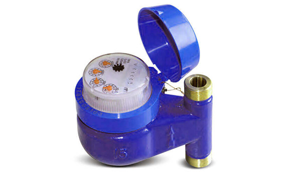
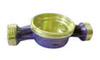
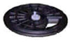
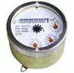
Multi-Jet Vane wheel type
Dry-dial Vertical Type Water Meters
It is a multi-jet dry type water meter for residential application in sizes 15mm-50mm for cold /hot water.
- Magnetic Drive. Lower transmission resistance.
- Magnetic shield, for external magnetic field protection.
- Sealed dry register ensures long time clear reading.
- External regulating device.
Accessories: 2pcs coupling, 2pcs coupling nuts and 2pcs washers.
Standards ComplianceTechnical data conform to international standard ISO 4064.
Optional Features- Register Sealed type: Dry type; Super-dry type.
- Accuracy: R=80.
- Size: 15~50mm.
- Cold / hot water.
- Non return valve.
- Reed switch option.
- Several lengths and connections availavle on request.
- Thread end type: BSP / NPT.
- Water temperature: 0.1 °C - 40°C for cold water meter.
- 0.1 °C ~ 90“C for hot water meter.
- Water pressure : 51.6Mpa (16 bar).
- The meter should be installed in vertical position with the direction of the flow as indicated by the arrow cast in the meter body with the register face upwards.
- Pipeling must be flushed before installation.
- The meter should be constantly full of water during operation.
- In the lower zone from qmin inclusive up to but excluding qtis ±5%.
- In the upper zone from qt inclusive up to and including qs is ±2%; ±3% for hot water meter.
Overall Dimension And Weight
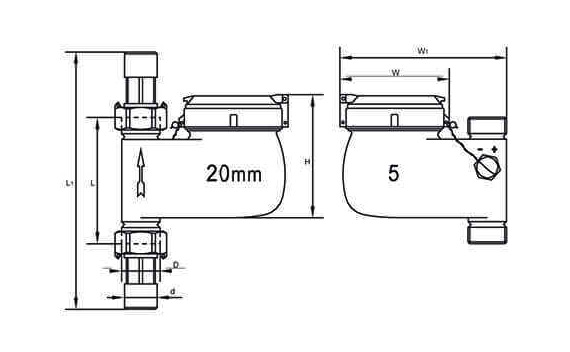
| DN (mm) | 15 | 20 | 25 | 32 | 40 | 50 |
| Size (inch) | 1/2" | 3/4" | 1” | 1-1/4" | 1-1/2” | 2" |
| L1 | 194 | 204 | 228 | 274 | 278 | 280 |
| L | 100 | 100 | 108 | 150 | 150 | 160 |
| H | 99.5 | 99.5 | 122.6 | 133.6 | 133.6 | 1875 |
| W1 | 133 | 137 | 166 | 220 | 228 | |
| Connecting Thread D | G3/4B | G1B | G11/4B | G11/2B | G2B | Flange connect |
| d | R 1/2 | R 3/4 | R 1 | R 1 1/4 | R 1 ½ |
Exploded View


| DN (mm) | 15 | 20 | 25 | 32 | 40 | 50 | |
| Size (inch) | 1/2" | 3/4" | 1" | 1-1/4" | 1-1/2" | 2" | |
| Q4(l/h) | 3125 | 5000 | 7875 | 12500 | 20000 | 31250 | |
| Q3(l/h) | 2500 | 4000 | 6300 | 10000 | 16000 | 25000 | |
| R=80 | Q2 (l/h) | 50 | 80 | 126 | 200 | 320 | 400 |
| Q1 (l/h) | 31.25 | 50 | 78.75 | 125 | 200 | 250 | |
| R=100 | Q2 (l/h) | 40 | 64 | 100.8 | 160 | 256 | 400 |
| Q1 (l/h) | 25 | 40 | 63 | 100 | 160 | 250 | |
| Max. Reading (m3) | 99,999 | 99,999 | 99,999 | 99,999 | 99,999 | 99 999 | |
| Min.Reading (Liter) | 0.05 | 0.05 | 0.05 | 0.05 | 0.05 | 0.05 | |
| Max.Pressure (Bar) | 16 | 16 | 16 | 16 | 16 | 16 | |
| Pressure Loss (P) | 63 | ||||||
| Max Temperature | T=50/90 | ||||||
| Pulse Output Option | Vmax=24V | ||||||
| lmax=100mA | |||||||
| Pmax=2W | |||||||
LXDG-15M~20M
Single-jet, vane wheel, dry-dial water meter (mini type with eight numberwheels)
- Measuring the volume of cold potable water passing through the pipeline.
- Single-jet, dry-dial, free rotating register, small in size and light in weight.
- Magneticdrive, Resistance to exterior magnet interference.
- Keep the reading clear in a long term service.
- Water temperature: 0.1 °C ~ 30°C.
- Water pressure: < 1 .0Mpa.
- Measuring accuracy conform to ISO 4064 class B standard.
- Available with different length on request.
- Body material: Brass / Plastic body.
- Register sealed: Dry-dial only.
- Size: 15-25mm for Brass body, 15-20 for plastic body. Cold/Hot water.
- Non-return valve.
- Reed switch option.
- Thread end type: BSP/NPT.
- In the lower zone from qmin inclusive up to but excluding qt is +5%.
- In the upper zone from qt inclusive up to and including qs is ±2%.
Dimensions
| Type | Size | L Length | B Width | H Height | D Connecting Thread |
| mm | |||||
| LXDG-15 | 15 | 110 | 67.5 | 72 | G3/4B |
| LXDG-20 | 20 | 130 | 67.5 | 73.5 | G1B |
Exploded View


| DN (mm) | 15 | 20 | |
| Size (inch) | 1/2" | 3/4" | |
| Q4(l/h) | 3125 | 5000 | |
| Q3(l/h) | 2500 | 4000 | |
| R=80 | Q2 (l/h) | 50 | 80 |
| Q1 (l/h) | 31.25 | 50 | |
| R=100 | Q2 (l/h) | 40 | 64 |
| Q1 (l/h) | 25 | 40 | |
| Max Reading (m3) | 99,999 | 99,999 | |
| Min Reading (Liter) | 0.05 | 005 | |
| Max.Pressure (Bar) | 16 | 16 | |
| Pressure Loss (P) | 63 | ||
| Max.Temperature | T=50 /90 | ||
| Pulse Output Option | Vmax=24V | ||
| lmax=100mA | |||
| Pmax=2W | |||
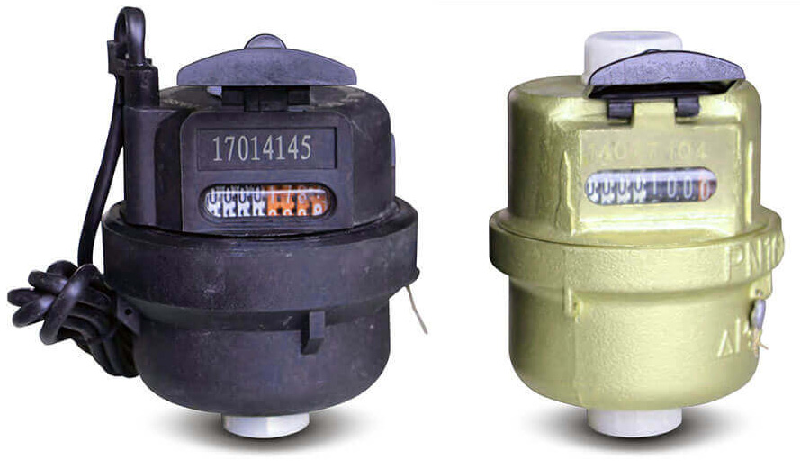
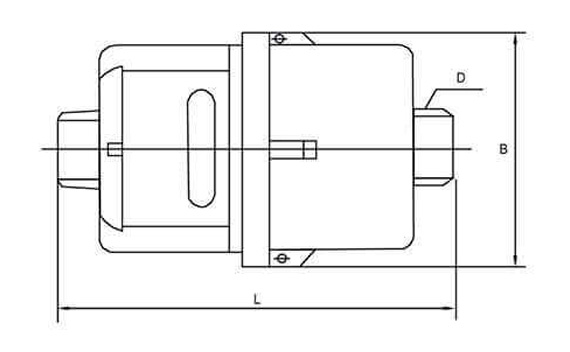
LXHY-15 -40
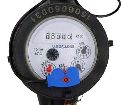
Rotary Piston Liquid Sealed Water Meter
This type of water meter can be used for a remote reading transmission system is equipped with a built-in sensor.
- Measuring the volume of cold portable water passing through the pipeline, Also suitable for pure water.
- The Max.Admissible water pressure 1,6MPa.
- Resisting water temperature: 50'C.
- Low start-up flow rate.
- Volumetric rotary piston principle ofmeasurement.
- LXHY-15—20 is no location limitation for installation.
- Accuracy is not to be affected wherever installed at a horizontal, vertical or inclined pipeline.
- Register is sealed with a special liquid to keep a clear reading in long term service.
- Mechanism use of high-quality material to ensure a stable characteristic.
- Accurate measurement with conformity to ISO 4064 class C.
- On request, the series can be equipped with a kind of remote transmission device.
| Magnet Position | Liter /Pulse |
| * 0.0001 | 1 |
| *0.001 | 10 |
Notice: The weight for pulse and without pulse is almost equal.
- Body material: Brass body / Plastic body.
- Size: Plastic body: DN15-20; Brass body: DN15-40.
- Different register can be choose:
| Dial Picture | Measure Unit |
 |
Measure Unit: CBM 8 WHEELS Four red, four white wheel. The minimum reading 1L |
 |
Measure Unit: CBM 8 WHEELS Three red, five white wheel. The minimum reading 10L |
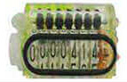 |
Measure Unit:UK Gallon 8 WHEELS One red, seven white wheel The minimum reading: 1 UK/Gallon |
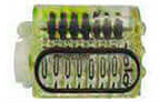 |
Measure Unit:UK Gallon 8 WHEELS All white wheel The minimum reading 10 UK Gallon |
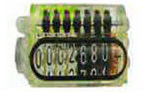 |
Measure Unit:US Gallon 8 WHEELS One red, three black, four white wheel The minimum reading: 1 US Gallon |
| Description | Unit | Hydraulic Data And Dimensions | |||||
| Nominal Size | mm (inch) | DN15 (1/2) | DN20 (3/4) | DN25 (1) | DN32 (1-1/4) | DN40 (1-1/2) | |
| Q. Error Limit ±2% | m'/h | 3.125 | 5 | 7875 | 12.5 | 20 | |
| Q Error Limit ±2% | m’/h | 2.5 | 4.0 | 6.3 | 10 | 16 | |
| Q Error Limit ±2% | l/h | 25 | 40 | 63 | 100 | 160 | |
| Q Error Limit ±5% | l/h | 15.6 | 25 | 394 | 625 | 100 | |
| Min.Reading I | 0.05 | 0.05 | 0.05 | 0.5 | 0.5 | ||
| Max.Reading | m’ | 9999.9999 | 9999.9999 | 9999.9999 | 99999.999 | 99999.999 | |
| MAP | MPa | 1 6 | 16 | 1.6 | 1.6 | 1.6 | |
| Press Loss P | MPa | ≤0.063 | ≤0.063 | ≤0.063 | ≤0.063 | ≤0.063 | |
| L | mm | 195 | 267 | 319 | 384 | 428 | |
| I | mm | 115 | 165 | 199 | 260 | 300 | |
| B | mm | 43 | 43 | 53 | 60 | 77 | |
| Weight | With Connections | Kg | 1 14 | 1.56 | 2 48 | 3.47 | 5.65 |
| Without Connections | Kg | 0 97 | 13 | 205 | 2 75 | 47 | |
Exploded View


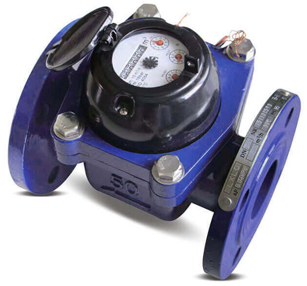
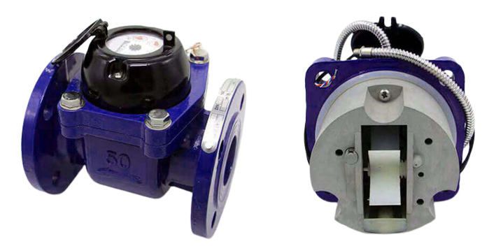
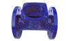
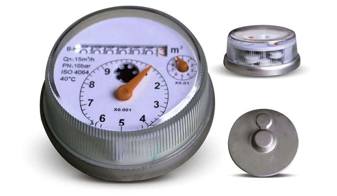
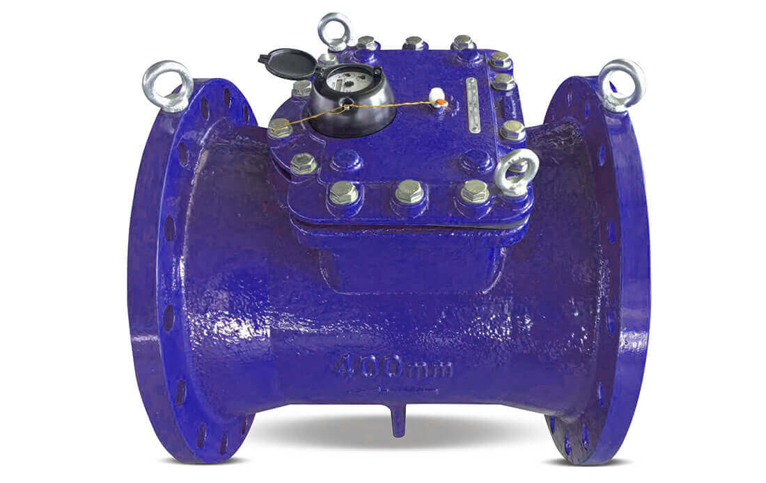
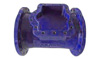
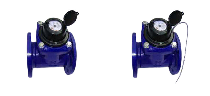
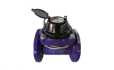
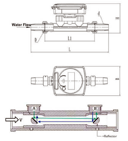
LXLC(R)-50~300(mm)
Removable element woltman cold (hot) water meter
This type of water meter can be used for a remote reading transmission system is equipped with a built-in sensor.
- Measuring the volume of cold (hot) water passing through the pipeline.
- Removable element structure, easy installation and maintenance, register for universal use within this range detachable without Removing the meter from the pipeline.
- Dry-dial. Magnetic drive sensitive action, small pressure loss.
- Vacuum sealed register ensures thedial keep free from fog and Keep the reading clear in a long term service.
- Selected high quality materialsforsteady & reliable charac teristic.
- Technical data conform to international standard ISO 4064.
- Plastic register, copper register and full glass register.
- Accuracy: R=50/80.
- Size: DN50-500mm.
- Cold/Hot water.
- Reed switch option.
- Flange standard can be choose.
- 360 degree rotate can be choose.
- Cast iron, Ductile iron, SS304.SS316 body can be choose.
- Working pressure: PN16/25.
- Color can be change on body and cover.
- Water temperature: 0.1'C~40'C (0.HD~90’C for hot water meter).
- Water pressure: PN10/16/25.
- In the lower zone from qmin inclusive up to but excluding qt is ±5%.
- In the upper zone from qt inclusive up to and including qs is ±2% (±3% for hot water meter).
Common Plastic Register
Copper Register
Full Glass Register
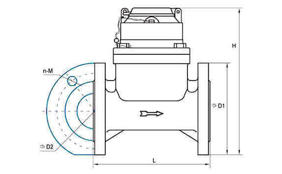
| Type | Size | L Length | H Height | Connecting Flange | ||
| Mm | D1 Outside Diameter | D2 BoltCircle Diameter | Connecting Bolts (n-M) | |||
| LXLC-50 | 50 | 200 | 261 | 165 | 125 | 4-M16 |
| LXLC-65 | 65 | 200 | 271 | 185 | 145 | 4-M16 |
| LXLC-80 | 80 | 225 | 279 | 200 | 160 | 8-M16 |
| LXLC-100 | 100 | 250 | 289 | 220 | 180 | 8-M16 |
| LXLC-125 | 125 | 250 | 299 | 250 | 210 | 8-M16 |
| LXLC-150 | 150 | 300 | 319 | 285 | 240 | 8-M20 |
| LXLC-200 | 200 | 350 | 346 | 340 | 295 | 8-M20(1.0DE ) |
| 12-M20(1.6MPa) | ||||||
| LXLC-250 | 250 | 450 | 450 | 395(1.0MPa) | 350(1 .0MPa) | 12-M20(1.0MPa) |
| 405(1.6MPa) | 355(1,6MPa) | 12-M24(1.6MPa) | ||||
| LXLC-300 | 300 | 500 | 478 | 445(1 .0MPa) | 400(1.0MPa) | 12-M20(1.0MPa) |
| 460(1,6MPa) | 410(1.6MPa) | 12-M24(1.6MPa) | ||||
NOTE: The flange dimension conforms to IS07005-2:1988 standard. Order for products of special requirements is also accepted.
| Size | Pulse Position |
| DN50-65 | 10/100/1000L/Pulse |
| DN80-200 | 100/1000L/Pulse |
| DN250-300 | 1000L/Pulse |
Exploded View


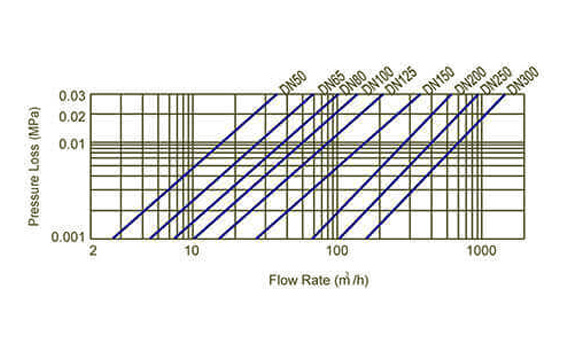
Flow Technique Specification
| Nominal Flow | Maximum | Permanent | Q2 Q>/Q | Q2/Q1 | Transitional | Minimum | Minimum Reading | Maximum Reading | |||||||
| Flow Q | Flow Q | Flow Q: | Flow Q, | Full Glass | Common Seal | Full Glass Seal | Common Seal | ||||||||
| DN | Seal | ||||||||||||||
| M3/h | M3/h | ||||||||||||||
| M3 | |||||||||||||||
| 31.3 | 25 | 50 | 1.6 | 0.8 | 0.5 | ||||||||||
| 50 | 4 | 2 | 0.0005 | 0 0002 | 999,999 | 999,999 | |||||||||
| 50 | 40 | 1.6 | 0.8 | 0.5 | |||||||||||
| 80 | 4 | 2 | |||||||||||||
| 65 | 50 50 | 4050 40 | 50 | 1.6 | 1.3 | 0.8 | |||||||||
| 65 | 50 | 4 | 3.2 | 0.0005 | 0.0002 | 999,999 | 999,999 | ||||||||
| 80 | 1.6 | 0.8 | 0.5 | ||||||||||||
| 4 | 2 | ||||||||||||||
| 50 | 1.6 | 2 | 1.3 | ||||||||||||
| 80 | 78.8 | 63 | 4 | 5 | 0.002 | 0.002 | 999,999 | 9,999,999 | |||||||
| 80 | 1.6 | 1.3 | 0.8 | ||||||||||||
| 4 | 32 | 2 | |||||||||||||
| 50 | 1.6 | 3.2 | 2 | ||||||||||||
| 100 | 125 | 100 | 4 | 8 | 0.002 | 0.002 | 999,999 | 9,999,999 | |||||||
| 80 | 1.6 | 2 | 1.3 | ||||||||||||
| 4 | 5 | ||||||||||||||
| 50 | 1.6 | 4 | 3.2 | ||||||||||||
| 4 | 12.8 | 0.002 | 0.002 | 999,999 | 9,999,999 | ||||||||||
| 125 | 200 | 160 | 80 | 1.6 | 3.2 | 2 | |||||||||
| 4 | 8 | ||||||||||||||
| 50 | 1.6 | 8 | 5 | ||||||||||||
| 150 | 312.5 | 250 | 4 | 20 | 0.002 | 0.002 | 999,999 | 9,999,999 | |||||||
| 80 | 1.6 | 5 | 3.1 | ||||||||||||
| 4 | 12.4 | ||||||||||||||
| 50 | 1.6 | 12.8 | 8 | ||||||||||||
| 200 | 500 | 400 | 4 | 32 | 0.002 | 0.002 | 999.999 | 9,999,999 | |||||||
| 80 | 1.6 | 8 | 5 | ||||||||||||
| 4 | 20 | ||||||||||||||
| 25 | 1.6 | 40.3 | 25.2 | ||||||||||||
| 250 | 787.5 | 630 | 4 | 100.8 | 0.02 | 0.02 | 9,999,999 | ######## | |||||||
| 50 | 1.6 | 20 | 12.6 | ||||||||||||
| 4 | 50.4 | ||||||||||||||
| 25 | 1.6 | 64 | 40 | ||||||||||||
| 300 | 1250 | 1000 | 4 | 160 | 0.02 | 0.02 | 9,999,999 | ######## | |||||||
| 50 | 6 | 32 | 20 | ||||||||||||
| 1 4 | 80 | ||||||||||||||
LXXG(R)-50 ~ 300(mm)
Irrigation Horizontal vane wheel, dry-dial cold (hot) water meter
This type of water meter can be used for a remote reading transmission system as equipped with a built-in sensor.
- Measuring the volume of cold (hot) water passing through the pipeline.
- Removableelementstructure, easy installation and maintenance.
- Dry-dial, Magnetic drive.
- Large flow capacity, small pressure loss.
- Resist water hummer and pollution.
- Vacuum sealed register ensures the dial keep free from
- condensation and keep the reading clear in a long termservice.
- Selected high quality materials for steady and reliable characteristic.
- Technical data conform to international standard ISO 4064.
- Plastic register, copper register and full glass register
- Accuracy: R=20.
- Size: DN50-300mm.
- Cold / Hot water.
- Reed switch option.
- Flange standard can be choose.
- 360 degree rotate can be choose.
- Cast iron, Ductile iron, SS304.SS316 body can be choose.
- Working pressure: PN16/25.
- Watertemperature:0.1"C~50°C (0.1*0—90'C for hot water meter).
- Water pressure: < 1.0Mpa (1.6MPa on request).
- In the lower zone from qmin inclusive up to but excluding qt is ±5%.
- In the upper zone from qt inclusive up to and including qs is ±2% (+3% for hot water meter).
| Size | L Length | H Height | Connecting Flange | |||
| Type | mm | D1 Outside Diameter | D2 BoltCircle Diameter | Connecting Bolts | ||
| (n-M) | ||||||
| LXXG-50 | 50 | 200 | 253 | 165 | 125 | 4-M16 |
| LXXG-65 | 65 | 200 | 268 | 185 | 145 | 4-M16 |
| LXXG-80 | 80 | 225 | 284 | 200 | 160 | 8-M16 |
| LXXG-100 | 100 | 250 | 295 | 220 | 180 | 8-M16 |
| LXXG-125 | 125 | 250 | 310 | 250 | 210 | 8-M16 |
| LXXG-150 | 150 | 300 | 339 | 285 | 240 | 8-M20 |
| LXXG-200 | 200 | 350 | 382 | 340 | 295 | 8-M20(1.0MPa) |
| 12-M20(1 6MPa) | ||||||
| LXXG-250 | 250 | 400 | 433 | 395 | 350 | 12-M20(1,0MPa) |
| 450 | 438 | 405 | 355 | 12-M24(1.6MPa) | ||
| LXXG-300 | 300 | 450 | 483 | 445 | 400 | 12-M20(1.0MPa) |
| 500 | 488 | 460 | 410 | 12-M24(1.SMPa) | ||
NOTE: The flange dimension conforms to IS07005-2:1988 standard. Order for products of special requirements is also accepted.
| Size | Pulse Position |
| DN50-200 | 100/1000L/Pulse |
| DN250-300 | 1000L/Pulse |
Exploded View


Flow Technique Specification
| Nominal Flow |
Maximum | Permanent | Maximum | Permanent | Minimum Reading | Maximum Reading | |||||
| Flow Q- | FlOW Q: | Q./Q | Q./Q | Flow Q: | Flow Q, | Full Glass Seal | Common Seal | Full Glass Seal | Common Seal | ||
| DN | m5/h | m7h | M3 | ||||||||
| 50 | 31.25 | 25 | 50 | 1.6 | 1.6 | 1 | 00005 | 0.0002 | 999,999 | 999,999 | |
| 4 | 4 | ||||||||||
| 65 | 50 | 40 | 25 | 1.6 | 2.6 | 1.6 | 0.002 | 0.002 | 999,999 | 9,999.999 | |
| 4 | 6.4 | ||||||||||
| 80 | 78.8 | 63 | 25 | 1.6 | 4 | 2.5 | 0.002 | 0.002 | 999,999 | 9,999,999 | |
| 4 | 10 | ||||||||||
| 100 | 125 | 100 | 25 | 1.6 | 6.4 | 4 | 0.002 | 0.002 | 999,999 | 9,999,999 | |
| 4 | 16 | ||||||||||
| 125 | 200 | 160 | 25 | 1.6 | 10.2 | 6.4 | 0002 | 0.002 | 999,999 | 9,999,999 | |
| 4 | 25.6 | ||||||||||
| 150 | 312.5 | 250 | 25 | 1.6 | 16 | 10 | 0.002 | 0.002 | 999.999 | 9,999,999 | |
| 4 | 40 | ||||||||||
| 200 | 500 | 400 | 25 | 1.6 | 25.6 | 15 | 0.002 | 0.002 | 999,999 | 9,999,999 | |
| 4 | 64 | ||||||||||
| 250 | 787.5 | 630 | 25 | 1.6 | 40.3 | 25.2 | 0.02 | 0.02 | 9.999,999 | 99,999.999 | |
| 4 | 100.8 | ||||||||||
| 300 | 1250 | 1000 | 25 | 1.6 | 64 | 40 | 0.02 | 002 | 9,999,999 | 99,999,999 | |
| 4 | 160 | ||||||||||
FULL GLASS SEALED RAGISTER TYPE WATER METER
Suitable for all large caliber dry-dial water meters.
- Measuring the volume of cold (hot) water passing through the pipeline.
- Accuracy: R=50/80
- Size: DN50-300mm
- Cold / Hot water
- Reed switch option
- Cast iron, Ductile iron, SS304,SS316 body can be choose.
- Working pressure: PN16/25
- Color can be change on body and cover.
- Never have mist, without any block when reading the counter.
- It make by special material, with good performance on anti-magnetism avoid, and more higher mechanical strength.
- Special appearance, more beautiful and with position to pulse.
- 7 digit wheel + 2 pointer on the counter, the maxi reading is 9,999,999m.
- Excellent sealed function, it can avoid condensation and mist, keep lo’ngtime clear reading.
- It very suitable for moist and temperature difference big country and region.
- Suitable for all large caliber dry-dial water meters.
LXLC(R)-350~600(mm)
Removable element woltman cold (hot) water meter
This type of water meter can be used for a remote reading transmission system as equipped with a built-in sensor.
- Measuring the volume of cold (hot) water passing through the pipeline.
- Removable element structure, easy installation and maintenance, registerfor universal use within this range detachable without Removing the meter from the pipeline.
- Dry-dial, Magneticdrive sensitive action, small pressure loss.
- Vacuum sealed register ensures the dial keep free from fog and Keep the reading clear in a long term service.
- Selected high quality materials for steady & reliable charac teristic.
- Technical data conform to international standard ISO 4064.
- Water temperature: 0.1'C~-50*C (0.1"C—90’C for hot water meter).
- Water pressure: £1Mpa (1.6MPa for special requirement).
- In the lower zone from qmin inclusive up to but excluding qt is ±5%.
- In the upper zone from qt inclusive up to and including qs is ±2% (±3% for hot water meter)
| Size | L | H | Connecting Flange | ||||
| Type | length | Height | D1 Outside Diameter | D2 Bolt Circle Diameter | Connecting Boits(n-M) | Working Pressure (MPa) | |
| Mm | |||||||
| LXLC -350 | 505 | 460 | 16-M20 | 1.0 | |||
| 350 | 500 | 590 | 520 | 470 | 16-M24 | 1.6 | |
| 555 | 490 | 16-M30 | 2.5 | ||||
| LXLC -400 | 565 | 515 | 16-M24 | 1.0 | |||
| 400 | 600 | 660 | 580 | 525 | 16-M27 | 1.6 | |
| 620 | 550 | 16-M33 | 2.5 | ||||
| LXLC -450 | 615 | 565 | 20-M24 | 1.0 | |||
| 450 | 600 | 700 | 640 | 585 | 20-M27 | 1.6 | |
| 670 | 600 | 20-M33 | 2.5 | ||||
| LXLC -500 | 670 | 620 | 20-M24 | 1.0 | |||
| 500 | 800 | 760 | 715 | 650 | 20-M30 | 1.6 | |
| 730 | 660 | 20-M33 | 2.5 | ||||
| LXLC -600 | 500 | 780 | 725 | 20-M27 | 1.0 | ||
| 600 | Or | 880 | 840 | 770 | 20-M33 | 1.6 | |
| 800 | 845 | 770 | 20-M36 | 2.5 | |||
NOTE: The flange dimension conforms to IS07005-2:1988 standard. Order for products of special requirements is alsoaccepted.
| Type | Size (mm) | Class | Qs Overload Flow | Qp Permanent Flow | Qt Transitional Flow | Qmin Min Flow | Min Reading |
Max. Reading |
|||
| M3/h | m3 | ||||||||||
| LXLC -350 | 350 | A | 1600 | 800 | 240 | 64 | 0.02 | 999,999,999 | |||
| B | 160 | 24 | |||||||||
| LXLC -400 | 400 | A | 2000 | 1000 | 300 | 80 | 0.02 | 999,999,999 | |||
| B | 200 | 30 | |||||||||
| LXLC -450 | 450 | A | 2000 | 1000 | 300 | 80 | 0.02 | 999,999,999 | |||
| B | 200 | 30 | |||||||||
| LXLC | 500 | A | 3000 | 1500 | 450 | 120 | 0.02 | 999.999.999 | |||
| -500 | B | 300 | 45 | ||||||||
| LXLC -600 | A | 6000 | 3000 | 900 | 240 | 0.02 | 999,999,999 | ||||
| 600 | B | 600 | 90 | ||||||||
Exploded View


LXLC(R)-50~600(mm)
Removable element woltman cold (hot) water meter
This type of water meter can be used for a remote reading transmission system as equipped with a built-in sensor.
- Measuring the volume of cold water passing through the pipeline
- Removable element structure, easy installation and maintenance, register for universal use within this range detachable without Removing the meter from the pipeline
- Dry-dial, Magnetic drive sensitive action, small pressure loss
- Vacuum sealed register ensures the dial keep free from fog and Keep the reading clear in a long term service
- Selected high quality materials for steady & reliable characteristic
- Technical data conform to international standard ISO 4064.
- Water temperature: 0.1 "C ~40"C (0.1 *C ~90'C for hot water meter)
- Water pressure: s1.6Mpa
- Maximum permissible errors in the lower zone from qmin inclusive up to but excluding qi is ±5%
(1) n the upper zone from qt inclusive up to and including qs is ±2% (±3% for hot water meter)
MAIN TECHNICAL SPECIFICATIONS
| Type | Size (mm) | Class | qs Overload Flow | qp Permanent Flow | qt Transitional Flow | qmin Min. Flow | Min. Reading | Max. Reading |
| m3/h | m3 | |||||||
| LXLC-50 | 50 | A | 30 | 15 | 4.5 | 1.2 | 0.0002 | 999,999 |
| B | 3.0 | 0.45 | ||||||
| LXLC-65 | 65 | A | 50 | 25 | 7.5 | 2.0 | 0.0002 | 999,999 |
| B | 5 | 0.75 | ||||||
| LXLC-80 | 80 | A | 80 | 40 | 12 | 3.2 | 0.002 | 999,999 |
| B | 8.0 | 1.2 | ||||||
| LXLC-100 | 100 | A | 120 | 60 | 18 | 4.8 | 0.002 | 999,999 |
| B | 12 | 1.8 | ||||||
| LXLC-125 | 125 | A | 200 | 100 | 30 | 8 | 0.002 | 999,999 |
| B | 20 | 3 | ||||||
| LXLC-150 | 150 | A | 300 | 150 | 45 | 12 | 0.002 | 999,999 |
| B | 30 | 4.5 | ||||||
| LXLC-200 | 200 | A | 500 | 250 | 75 | 20 | 0.002 | 999,999 |
| B | 50 | 7.5 | ||||||
| LXLC-250 | 250 | A | 800 | 400 | 120 | 32 | 0.002 | 999,999 |
| B | 80 | 12 | ||||||
| LXLC-300 | 300 | A | 1200 | 600 | 180 | 48 | 0.02 | 9,999,999 |
| B | 120 | 18 | ||||||
| LXLC-400 | 400 | A | 2000 | 1000 | 0.1 | 9,999,999 | ||
| B | 200 | 30 | ||||||
| LXLC-500 | 500 | A | 3000 | 1500 | 0.1 | 9,999,999 | ||
| B | 300 | 45 | ||||||
| LXLC-600 | 600 | A | 5000 | 2500 | 0.1 | 9,999,999 | ||
| B | 500 | 75 | ||||||
DIMENSIONS
| Type | Size | L Length | H Height | Connecting flange | ||
| D1 Outside diameter | D2 Bolt circle diameter | Connecting Bolts (n-M) | ||||
| Mm | ||||||
| LXLC-50 | 50 | 200 | 261 | 165 | 125 | 4-M16 |
| LXLC-65 | 65 | 200 | 271 | 185 | 145 | 4-M16 |
| LXLC-80 | 80 | 225 | 279 | 200 | 160 | 8-M16 |
| LXLC-100 | 100 | 250 | 289 | 220 | 180 | 8-M16 |
| LXLC-125 | 125 | 250 | 299 | 250 | 210 | 8-M16 |
| LXLC-150 | 150 | 300 | 319 | 285 | 240 | 8-M20 |
| LXLC-200 | 200 | 350 | 346 | 340 | 295 | 8-M20(1.0MPa) 12-M20(1.6MPa) |
| LXLC-250 | 250 | 400 | 434 | 395 | 350 | 12-M20(1.0MPa) |
| 450 | 434 | 405 | 355 | 12-M24(1.6MPa) | ||
| LXLC-300 | 300 | 450 | 459 | 445 | 400 | 12-M20(1.0MPa) |
| 500 | 459 | 460 | 410 | 12-M24(1.6MPa) | ||
| LXLC-400 | 400 | 500 | 621 | 565 | 515 | 16-M24(1.0MPa) |
| 500 | 621 | 565 | 525 | 16- M27(1.6MPa) | ||
| LXLC-500 | 500 | 500 | 725 | 670 | 620 | 20-M24(1.0MPa) |
| 500 | 725 | 670 | 650 | 20- M30(1,6MPa) | ||
| LXLC-600 | 600 | 600 | 840 | 780 | 725 | 20-M26(1.0MPa) |
NOTE: The flange dimension conforms to IS07005-2:1988 standard. Order for products of special requirements is also accepted.
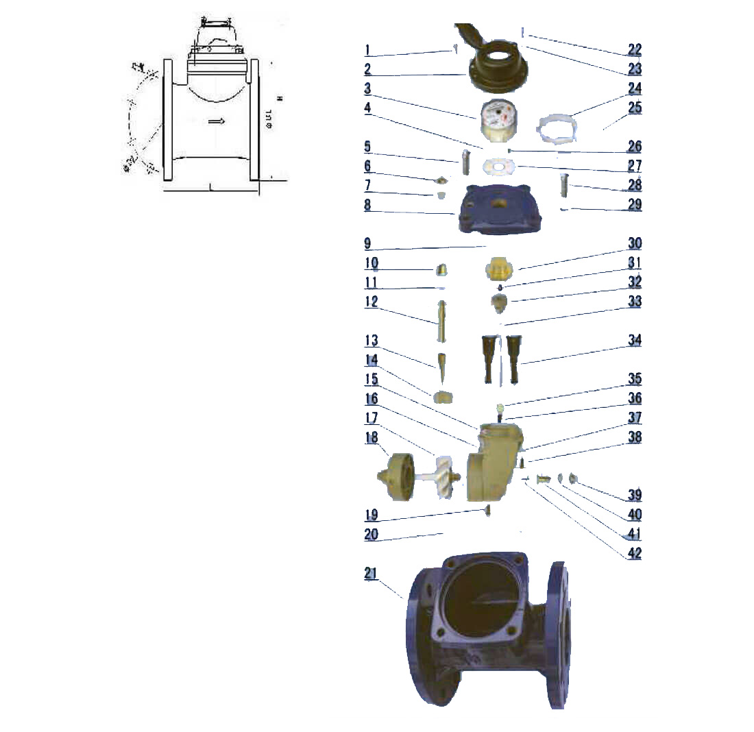
| Code | Description | Material | QTY |
| 1 | Screw For Sealing | Stainless Steel | 2 |
| 2 | Cover With Lid | Assembly | 1 |
| 3 | Sealed Register | Assembly | 1 |
| 4 | Position Pin | Stainless Steel | 1 |
| 5 | Lead Seal Bolt | Stainless Steel | 2 |
| 6 | Adjusting Nut | Brass | 1 |
| 7 | Gasket | Brass | 1 |
| 8 | Flange Cover | Cast Iron | 1 |
| 9 | O-ring | Silicon Rubber | 1 |
| 10 | Bush | Brass | 1 |
| 11 | Gasket | Synthetic Rubber | 1 |
| 12 | Adjusting Lever | Brass | 1 |
| 13 | Connecting Lever | MPPO | 1 |
| 14 | Adjusting Plate | MPPO | 1 |
| 15 | Support | MPPO | 1 |
| 16 | Bolt | Brass | 1 |
| 17 | Turbine Component | Assembly | 1 |
| 18 | Rectifier | MPPO | 1 |
| 19 | Screw | Brass | 1 |
| 20 | O-ring | Synthetic Rubber | 1 |
| 21 | Body | Ductile/Cast Iron | 1 |
| 22 | Screw M4><20 | Stainless Steel | 2 |
| 23 | Gasket | Stainless Steel | 3 |
| 24 | Retainer | ABS | 1 |
| 25 | Fixing pin | Brass | 1 |
| 26 | Screw | Brass | 4 |
| 27 | Support | ABS | 1 |
| 28 | Bolt M12><35 | Stainless Steel | 2 |
| 29 | Gasket | Stainless Steel | 4 |
| 30 | Upper Bearing Plate | Brass | 1 |
| 31 | Upper Bearing | Nylon With Graphite | 1 |
| 32 | Magnet Component | Component | 1 |
| 33 | Transmission Shaft | Stainless Steel | 1 |
| 34 | Sheath | MPPO | 2 |
| 35 | Bevel Gear | Nylon | 1 |
| 36 | Lower Bearing | Nylon With Graphite | 1 |
| 37 | Gasket | Brass | 4 |
| 38 | Screw | Brass | 3 |
| 39 | Nut | Brass | 1 |
| 40 | Gasket | Brass | 1 |
| 41 | Turbine Shaft Hold | Brass | 1 |
| 42 | Turbine Shaft | Tungsten Steel | 1 |
LXCLG(R)-50 ~ 200(mm)
Vertical removable element woltman cold (hot) water meter
This type of water meter can be used for a remote reading transmission system as equipped with a built-in sensor.
- Measuring the volume of cold (hot) water passing through the pipeline.
- Removable element structure, easy installation and maintenance, registerforuniversal use within this range detachable without Removing the meter from the pipeline.
- Dry-dial, Magnetic drive sensitive action, small pressure loss.
- Vacuum sealed register ensures the dial keep free from fog and Keep the reading clear in a long term service.
- Selected high quality materials for steady & reliable characteristic.
- Technical data conform to international standard ISO 4064.
- Water temperature: 0.1‘C~ 40‘C (0.1 *C~-90'C for hot water meter).
- Water pressure: < 1 Mpa (1,6MPa for special requirement).
| TypeTType | Length | Height | Connecting Flange | |||||
| L | H H H | h | G | D1Outside Diameter | D2 Boil Circle Diameter | Connecting Bolts (n-M) (n-M) | ||
| mm | ||||||||
| 40 | 280 | 228 | 85 | 268 | 150 | 110 | 4-M16 | |
| 245 | 218 | 75 | 260 | Thread end G2B | ||||
| 50 | 280 | 228 | 85 | 268 | 165 | 125 | 4-M16 | |
| 80S | 225 | 282 | 103 | 344 | 200 | 160 | 8-M16 | |
| 80 | 370 | |||||||
| 100S | 250 | 116 | 350 | 220 | 180 | 8-M16 | ||
| 100 | 370 | |||||||
| 150 | 500 | 430 | 155 | 565 | 285 | 240 | 8-M20 | |
| 200 | 500 | 505 | 190 | 384 | 340 | 295 | 8-M20 12-M20 (MAP16) | |
NOTE: The flange dimension conforms to IS07005-2:1988 standard. Order for products of special requirements is also accepted.
| Maximum | Permanent | Maximum | Permanent | Max. Reading | Min. Reading | ||||
| Type | Flow Q. | Flow Qs | Q3IQ1 | Q2/Q1 | Flow Q.- | Flow Qi | Full Glass Register | Plastic Register | |
| m’/h | n | /h | M3 | ||||||
| 160 | 1.6 | 04 | 0.25 | ||||||
| 40 | 50 | 40 | 6,3 | 1.6 | 999999 | 0.0005 | 0.0002 | ||
| 200 | 1.6 | 0.32 | 0.2 | ||||||
| 6.3 | 1.26 | ||||||||
| 160 | 1.6 | 0.4 | 0.25 | ||||||
| 50 | 50 | 40 | 6.3 | 1.6 | 999999 | 0.0005 | 00002 | ||
| 200 | 1.6 | 032 | 0.2 | ||||||
| 6.3 | 1.26 | ||||||||
| 160 | 1.6 | 0.64 | 0.4 | ||||||
| 80 | 78.8 | 63 | 6.3 | 2.5 | 999999 | 0.0005 | 0.0002 | ||
| 200 | 1.6 | 0.5 | 0.32 | ||||||
| 6.3 | 2 | ||||||||
| 160 | 1.6 | 1 | 0.63 | ||||||
| 100 | 125 | 100 | 6.3 | 3.94 | 999999 | 0.0005 | 0.0002 | ||
| 200 | 1.6 | 0.8 | 0.5 | ||||||
| 6.3 | 3.2 | ||||||||
| 160 | 1.6 | 2.56 | 1.6 | ||||||
| 150 | 313 | 250 | 6.3 | 10 | 999999 | 0.0005 | 0.0002 | ||
| 200 | 16 | 2 | 1.25 | ||||||
| 6.3 | 7.9 | ||||||||
| 160 | 1.6 | 4 | 2.5 | ||||||
| 200 | 500 | 400 | 6.3 | 16 | 999999 | 00005 | 0.0002 | ||
| 200 | 16 | 3.2 | 9 | ||||||
| 6.3 | 12.6 | ||||||||
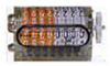
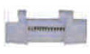
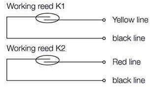
Please see the diagram of the two reed switches system below, the two reed switches would be operated “ON” OR ’OFF” respectively by the magnet fitted to the pointer or gear during its running on the register, but never "ON” at the same time .unless the out- magnet attackes.
The two reed switches operate two “ON” and two “OFF” in one round of the pointer or the gear means one signal output, this principle prevent the loss or overcounting of the signal output due to the switches joggling or the pipe vibrating, so assures reliability of the signal output.
WarrantyAll meters will be guaranteed against defects in workmanship and materials for a period of one (1) year from the date of acceptance. Defective meters or parts discovered within this period shall be replaced without charge upon return to the SH-MECH Meters.
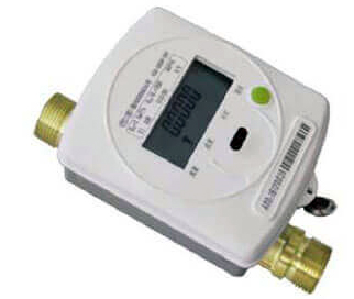
PHOTOELECTRIC DIRECT READING WATER METER
DN15-50
- Through the coding and decoding table word round will count "direct reading" came out, a word on the physical location of wheel digital compiled.
- The system (or handwritten device) reading list to transfer within a table, need not battery, also do not need the power to maintain data.
- And decoder meter reading instant complete decoding, send out data, the output of the table and the Numbers of the table ZiPan reading without deviation, shaking, backflow, strong magnetic interference can influence the decoding readings.
- Table has unique identity code, namely table address (the factory Numbers): eight or 12 or 14 digitsa.
- Through the bus remote transmission dosage information and other information.
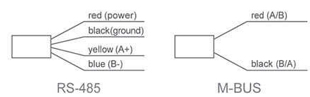
- And integration, to provide RS-485 / MBUS bus transmission, can work alone can also component network system, information from the special handwritten copy read or system alone networking copy read.
- "0" power consumption, lower failure rate, longer life.
- Intelligent electronic unit completely sealed in thecounter, and water isolation from the outside world water and moisture erosion.
- ISO 4064 Class B for horizontal Installation.
- < Electronicremote-reading water meter>(CJ/T 224-2012).
- Water temperature: 0.1*C~+50’C.
- Water pressure:< 1.6 MPa.
| Item | Communication Mode | RS-485 | MBUS |
| 1 | Working voltage | 9V-15V | 24V-42V |
| 2 | Static current | <1mA | <2mA |
| 3 | Wording current | <5mA | s10mA |
| 4 | Communication protocol |
DL/T645, CJ/T 188 (or customer requirements1 | |
| 5 | Communication rate | 1200/2400Baud | |
| Type | Size (mm) | Class | Qs Overload Flow | Qp Permanent Flow | qt Transitional Flow | q,min Minimum Flow | Minimum Reading | Maximum Reading |
| m3/h | L/h | m3 | ||||||
| LXSG-15 | 15 | B | 3 | 1.5 | 120 | 30 | 0.00005 | 99,999 |
| LXSG-20 | 20 | B | 5 | 2.5 | 200 | 50 | 0.00005 | 99,999 |
| LXSG-25 | 25 | B | 7 | 3.5 | 280 | 70 | 0.00005 | 99,999 |
| LXSG-32 | 32 | B | 12 | 6.0 | 480 | 120 | 0.00005 | 99,999 |
| LXSG-40 | 40 | B | 20 | 10 | 800 | 200 | 0.00005 | 99,999 |
| LXSG-50 | 50 | B | 30 | 15 | 3000 | 450 | 0.00005 | 99,999 |
- In the lower zone from Qmin inclusive up to but excluding Qp is ±5%.
- In the upper zone from Qp inclusive up to and including Qs is ±2%.
| Type | Size | L Length | B Width | H Height | d Connecting Thread |
| MM | |||||
| LXSG-15 | 15 | 165 | 98 | 116 | G3/4B |
| LXSG-20 | 20 | 190 | 98 | 117 | G1B |
| LXSG-25 | 25 | 260 | 103.5 | 124 | G11/«B |
| LXSG-32 | 32 | 260 | 1035 | 124 | GIV2B |
| LXSG-40 | 40 | 300 | 125 | 162 | G2B |
| LXSG-50 | 300 | 125 | 162 | G27aB | |
| 50 | 280 | 160 | 187.5 | Flange connectlSO 7005-2:1988 (|>D=125 | |
| Type | Size (mm) | Class | qs Overload Flow | qn Permanent Flow | qt Transitional Flow | qmin Minimum Flow | Minimum Reading | Maximum Reading |
| m3/h | m3 | |||||||
| LXDG-15/ZD | 15 | B | 3.0 | 1.5 | 0.12 | 0.03 | 0.0001 | 99.999 |
| LXDG-20/ZD | 20 | 5.0 | 2.5 | 0.2 | 0.05 | 0.0001 | 99,999 | |
- In the lower zone from Qmin inclusive up to but excluding Qp is ±5%.
- In the upper zone from Qp inclusive up to and including Qs is ±2%.
| Type | Size | Length | Width | Height | Connecting Thread | |
| Mm | ||||||
| LXDG-15/ZD | 15 | 110 | 67.5 | 72 | G3/4B | |
| LXDG-20/ZD | 20 | 130 | 67.5 | 73.5 | G1B | |
| Type | Size (mm) | Class | Qs Overload Flow | Qn Permanent Flow | qt Transitional Flow | Qmn Minimum Flow | Minimum Reading | Maximum Reading |
| M3/h | m3 | |||||||
| LXLC-50/ZD | 50 | A | 30 | 15 | 4.5 | 1.2 | 0.0002 | 99.999 |
| B | 3.0 | 0.45 | ||||||
| LXLC-66/ZD | 65 | A | 50 | 25 | 7.5 | 2.0 | 0.0002 | 99.999 |
| B | 5 | 0.75 | ||||||
| LXLC-80/ZD | 80 | A | 80 | 40 | 12 | 3.2 | 0.002 | 99,999 |
| B | 8.0 | 1.2 | ||||||
| LXLC-100/ZD | 100 | A | 120 | 60 | 18 | 4.8 | 0.002 | 99,999 |
| B | 12 | 1.8 | ||||||
| LXLC-125/ZD | 100 | A | 200 | 100 | 30 | 8 | 0.002 | 99,999 |
|
B |
|
20 | 3 | ||||
| LXLC-150/ZD | 150 | A | 300 | 150 | 45 | 12 | 0.002 | 99,999 |
| B | 30 | 4.5 | ||||||
| LXLC-200/ZD | 200 | A | 500 | 250 | 75 | 20 | 0.002 | 99,999 |
| B | 50 | 7.5 | ||||||
| LXLC-250/ZD | 250 | A | 800 | 400 | 120 | 32 | 0.002 | 99,999 |
| B | 80 | 12 | ||||||
| LXLC-300/ZD | 300 | A | 1200 | 600 | 180 | 48 | 0.02 | 99.999 |
| B | 120 | 18 | ||||||
- In the lower zone from Qmin inclusive up to but excluding Qt is ±5%.
- In the upper zone from Qt inclusive up to and including Qs is ±2%.
- In the lower zone from Qmin inclusive up to but excluding Qt is +5%.
- In the upper zone from Qt inclusive up to and including Qs is ±3%.
| Type | Size | L | H | ConnectingFlang | ||
| Length | Height | D1Outside | D2Bolt circle | Connecting Bolts (n-M) | ||
| mm | diameter | diameter | ||||
| LXLC-50/ZD | 50 | 200 | 261 | 165 | 125 | 4-M16 |
| LXLC-65/ZD | 50 | 200 | 261 | 165 | 125 | 4-M16 |
| LXLC-80/ZD | 80 | 225 | 279 | 200 | 160 | 8-M16 |
| LXLC-100/ZD | 100 | 250 | 289 | 220 | 180 | 8-M16 |
| LXLC-125/ZD | 125 | 250 | 299 | 250 | 210 | 8-M16 |
| LXLC-150/ZD | 150 | 300 | 319 | 285 | 240 | 8-M20 |
| LXLC-200/ZD | 200 | 350 | 346 | 340 | 295 | 8-M20(1.0MPa) |
| 2-M20(1.6MPa) | ||||||
| LXLC-250/ZD | 250 | 400 | 434 | 395 | 350 | 12-M20(1.0MPa) |
| 450 | 434 | 405 | 355 | 12-M24(1,6MPa) | ||
| LXLC-300/ZD | 300 | 450 | 459 | 445 | 400 | 12-M20(1.0MPa) |
| 500 | 459 | 460 | 410 | 12-M24(1,6MPa) | ||
- The meter should be installed in horizontal position with the direction of the flow as in dicated by the arrow cast in the meter body with the register face upwards.
- Pipeline must be flushed before installation.
- The meter should be constantly full of waterduring operation.
- The meter must have 10 diameters straight pipe ahead of the meter and 5 diameters straight pipe after to insure proper flow through the meter.
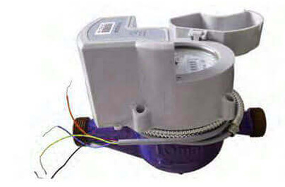
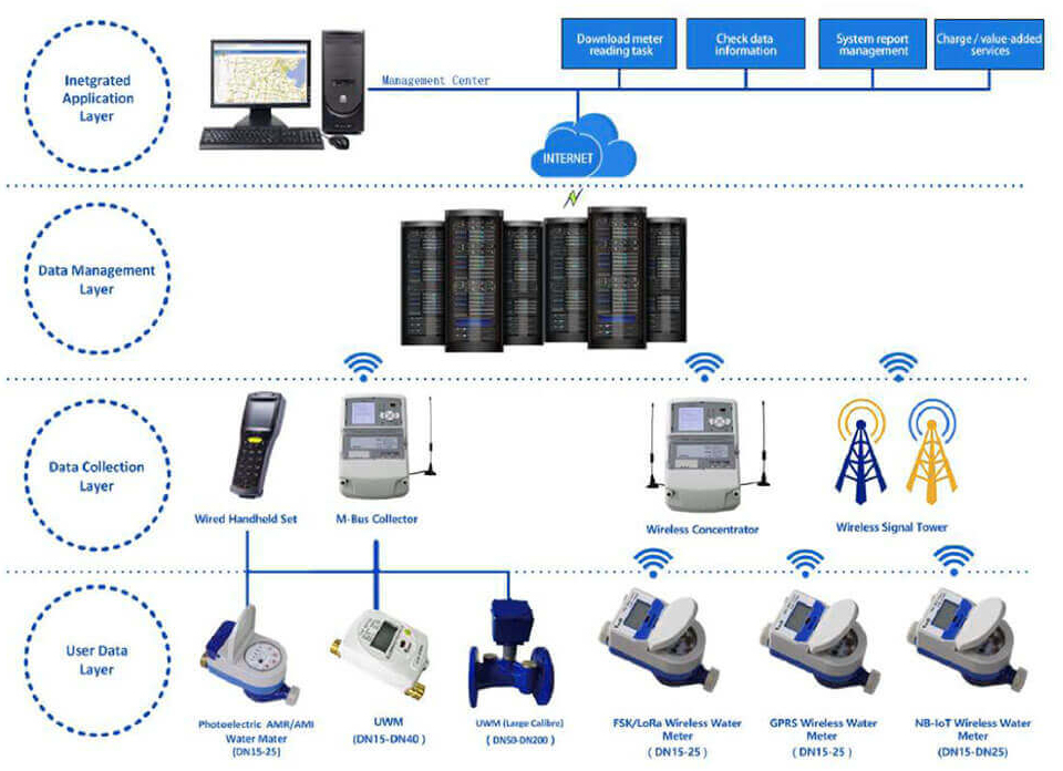
AMR SYSTEM INTRODUCTION
Simple is Smart.....
- The structure diagram of the whole system is as follows,
- The server send the commands tothe data concentrator through the network,
- Further, the concentrator transforms the received commands into the wireless signal and send the signal to the water meters;
- The water meters respond and execute the actions accordingly, after receiving the commands;
- The meters deliver the result or data back to the data center as per the original route after the actions finished
- Quality Gurantee: Battery over 6 years; Water meter 2 years; Support install guide & test in site;
- Date sheet can be send to other management system easily.
LORA Wireless
AMR Water Meter
- With anti-magnetic interference (unction that when the two reed switches pick up caused by the magnetic inerference. the valve closes oft automatically; It automatically opens when the interference steps.
- With the battery voltage detection function it can pass the power-off information to the management platform when the battery almost runs out. facilitating the administrator to find that;
- Module with automatic data storage function when power down arises, assuring the data won't lost when power down, and when the power supply recovers, it is able to continue to work properly.
- 7 layers 8 type price to support market demand.
- The joint of the RF module and the base meter uses the integrated structure, with built-in antenna, reducing the damage of antenna in the process of installation;
- The communication distance of the wireless module can be optimized according to the different demands, peer-to-peer communication distance no less than 1000m(ln open field condition, thus, during practical construction, the transfer impedance need to be considered);
- Use of LoRa transfer mode that can drastically extend the communication d stance after the repeaterfs) installed;
- The module uses of deep dormancy lime design, it is able to completely close the wireless module during the deep dormancy time period (not in operation during night time). which drastically help reduce the power consumption;
- Whole circuit board uses of ultra low power consumption design, power supply by high capacity lithium battery, battery life over 6 years:
- Is able to set up the metering devices by the handset reader and check the original data and data from meter reading;
- AMI (unction that the system is able to control the shut on/off of the valve on real time by the help of the valve.
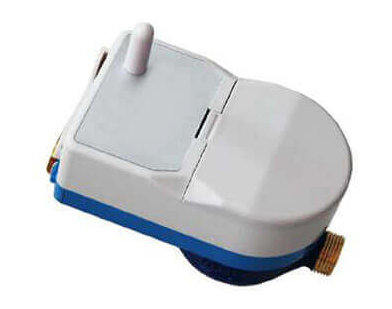
LoRa wireless water meter using of advanced wireless transmission technology, it transforms metered information of conventional mechanical water meter into electrical signal have it stored by micro-electronics control circuit. It is able to automatically read the metering data via wireless remote network and control the close open of the valve.
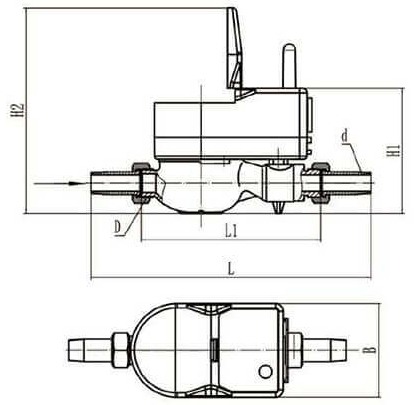
Installation specs & dimension| Nominal Diameter | Length L | Length L1 | Width B | Height H1 | Height H2 | Connecting Thread | ||
| mm | d | D | ||||||
| 15 | 258 | 165 | 90 | 112 | 184 | R1/2 | G3/4B | |
| 20 | 299 | 195 | 90 | 112 | 184 | R3/4 | G1B | |
| 25 | 345 | 225 | 90 | 114 | 186 | R1 | G1 1/4B | |
| item | Unit | Details | ||
| Nominal diameter | mm | 15 20 25 | ||
| Q3/Q1 | R80 | |||
| Overload flow(Q4) | M3/h | 3.125 | 5 | 7.875 |
| Nominal flow(Q3) | M3/h | 2.5 | 4 | 6.3 |
| Transitional flow(Q2) | M3/h | 0.05 | 0.08 | 0.13 |
| Minimum (low(Q1) | M3/h | 0031 | 005 | 0.08 |
| Accuracy class | Class 2 | |||
| Maximum indication | m399999 | |||
| Temperature class | T30.T90 | |||
| Pressure class | MAP10 | |||
| Pressure loss class | Δp63 | |||
| Few profile sensitivity class | U10/D5 | |||
| Environmental class | Class B | |||
| Electromagnetic environment class | E1 | |||
| Static current | uA<10 | |||
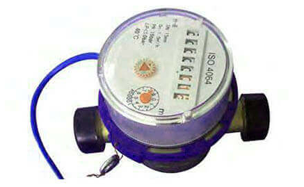
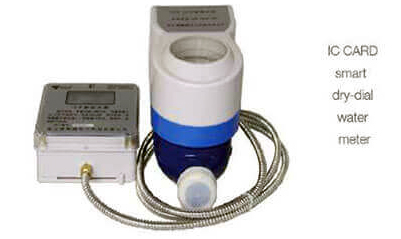
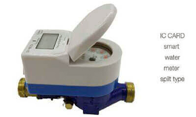
Prepaid Water Meter
Brief introduction
The prepaid water meter is a smart water meter with both mechanical and electronic readings. It can control users overspend by prepaying for an 1C card II is suited to the metering and billing of urban residential water use, using water after fee paid that gets rid of the Inconvenience of on-site visit for meter reading and tariffing.
Product features- Contactless radio frequency card technology, wireless data Transmission, hermetically sealed response zone for 1C card Without card groove, tamperproof.
- Valve use of anti-blockage suspension construction, small valve torque eliminates any risk of blockage .shut-on/off valve with small torque, improving the reliability and life span of the valve.
- Use of hermetically sealed construction design, water-tight, moisture proof.
- Use of drawer-type battery box construction, user can easily change the battery.
- Regularly close/open the valve to remove the contaminant on the surface of the ball valve.
- Stepped tariffs, 3 stepped water volume adjustable,3 stepped unit price settable.
- Is resistant to magnetic interference automatically close the valve under under voltage condition.
- Valve inner leakage < 2L/h
Main technical data
| Item | Unit | Details | |
| Nominal diameter | mm | 15 20 25 | |
| Q3/Q1 | R80 | ||
| Overload flow(Q4) | M3/h | 3.125 5 | 7.875 |
| Nominal flow(G3) | M3/h | 2.5 4 | 6.3 |
| Transitional flow(Q2) | M3/h | 0.05 0.08 | 0.13 |
| Minimum flow(Q1) | M3/h | 0.031 0.05 | 008 |
| Accuracy class | Class 2 | ||
| Maximum indication | M399999 | ||
| Temperature class | T30.T90 | ||
| Pressure class | MAP10 | ||
| Pressure loss class | Δp63 | ||
| Row prefile sensitivity class | U10/D5 | ||
| Envfonmental class | Class B | ||
| Electromagnetic environment class | E1 | ||
| Static current | uA<10 | ||
- Maximum permissible error between Q1 and Q2(excluded) is ±5% in flow low area
- When the water temperature is not higher than 30 C, maximum permissible error between 02 and Q4 {included is ±2% in flow high area.
- When the water temperature is higher than 30 C, maximum permissible error between 02 and Q4(included) is ±3% in flow high area.
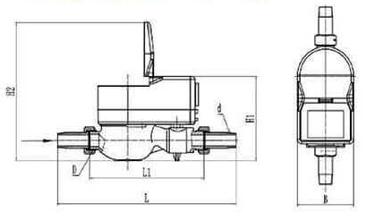
| Nominal Diameter | Length L | Length L1 | Width B | Height H1 | Height H2 | Connecting Thread | |
| mm | d | D | |||||
| 15 | 258 | 165 | 90 | 112 | 184 | R1/2 | G3/4B |
| 20 | 299 | 195 | 90 | 112 | 184 | R3/4 | G1B |
| 25 | 345 | 225 | 90 | 114 | 186 | R1 | G1 V4B |
| Item | Fault display | Fault explanation | Elimination methods |
| 1 | Under voltage | Low battery | contact the manufacturer |
| 2 | Flow | Flow sensor signal failure | |
| 3 | Valve open/close | Valve sticking, rusting or scaling | |
| 4 | can not read card | Write card error or take the wrong card | go to water supply department to test the card |
Ultrasonic Water Meter
- No mechanical movable parts, Impurities in water can't be affected, Long service life.
- Compared with the traditional mechanical water meter, the ultrasonic water meter can be measured and has wide range of measurement.
- It can be measured when it has very small traffic .
- There are many alarm functions: Battery voltage can alarm, empty tubes or pipes that are not full of water, transducer fault alarm and more
- Low-power design and the use of high-energy batteries, can work tor 6 years or more.
- It has infrared optical interface and use of infrared meter reading instruments can be achieved on-site meter reading.
- The communication interface is M-BUS and Rs485,lt can easily achieve remote real-time monitoring and management on the LAN.
Ultrasonic water meter is to detect ultrasonic waves in the water downstream and countercurrent propagation time difference, This new all-electronic water meter is calculated by the program analysis and processing of water flow rate and then calculate the water flow
Installation specs & dimension| Nominal Diameter | Length L | Length L1 | Width B | Height H1 | Connecting Thread | |
| Mm | d | D | ||||
| 15 | 258 | 165 | 95 | 95 | R1/2B | G3/4B |
| 20 | 299 | 195 | 95 | 100 | R3/4 | G1B |
| 25 | 345 | 225 | 95 | 106 | R1 | G1 1/4B |
| 32 | 305 | 180 | 65 | 120 | R1 1/4 | G1 1/2B |
| 40 | 330 | 200 | 95 | 125 | R1 1/2 | G2B |
| Item | Unit | Details | ||||
| Nominal diameter | mm | 15 | 20 | 25 | 32 | 40 |
| Q3/01 | R200 | |||||
| overload flow(Q4) | M3/h | 3.125 | 5 | 7.875 | 12.5 | 20 |
| Nominal flow(Q3) | M3/h | 2.5 | 4 | 6.3 | 10 | 16 |
| Transitional flow(Q2) | M3/h | 0.02 | 0.032 | 0.05 | 0.08 | 0.128 |
| Minimum flow(Q1) | M3/h | 0.013 | 0.02 | 0.032 | 0.05 | 0.08 |
| Accuracy class | Class B | |||||
| Battery life | 8years | |||||
| Temperature class | T30/T50 | |||||
| Pressure class | ≤0.053Mpa | |||||
| Pressure loss class | Δp63 | |||||
| Flow prefile sensitivity class | U10/D5 | |||||
| Environmental class | Class B,M1 | |||||
| Electromagnetic environment class | E1 | |||||
| Working pressure | 1.6Mpa | |||||
| Max flow indication | 999999.9m3 | |||||
| Installation Position | Horizontal or Vertical | |||||
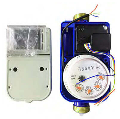
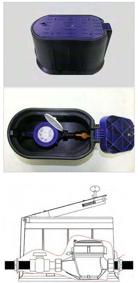
BASIS SMART WATER METER WITH VALVE
Small type basis smart water meter measuring the total volume of portable water passing through the pipeline. The product use the special small mechanism and low torque valve, it with the feature that volume is small, weight is light and high precision, valve is easy open and close. To be basis of smart water meters it can save the space, make the smart water meter more small and beautiful, it is the very good choice to be basis of smart water meters.
The System Include- Brass body, multi-jet, dry-dial mechanism water meter with brass connection.
- With valve to open/close the pipeline.
- With.
- Cold water meters: 0.1 C ~30 C.
- Hot water meters: 30 C -90 C.
- Water pressure: < 1MPa.
- Q3/Q1=80, Q2/Q1=1.6, Q4/Q3=1.25
| Diameter | Class level | Qs Overload flow | Qp Permanent flow | Qt Transitional flow | Qmin Minimum flow |
| mm | m3/h | ||||
| 15 | 2 | 3.1 | 2.5 | 0.050 | 0.031 |
| 20 | 2 | 5.0 | 4.0 | 0.080 | 0.050 |
| 25 | 2 | 7.9 | 6.3 | 0.126 | 0.079 |
- In the lowerzone from Qmin inclusive up to but excluding Qt is ±3%.
- In the upper zone from Qt inclusive up to and including Qs is±2% ; Hot water meter is ±3%.
- It use reed switch send out and collect the signal, when the two reed switch each one closed one time, it will produce one pulse, the two reed switch will not closed in the same time. The working principle will avoid the more additional signal principle, it will guarantee the mechanical parts reading same with LCD display. It also can avoid the outside magnetic field interference, if there are any interference, the two reed switch will closed in the same time.
- Reed switch closed resistance: < 1Q; open resistance:>10M Q,the best closed/open resistance value more smaller more better, it will save the consumption.
- When collect the signal to avoid the reed switch additional shake, when test the closed situation, it should be collect delay 0.5S~1S.After the short time, the reed switch still closed, it will be effective.
- Torque
| Press(MPa) | New installed valve most biggest torque in Permanent flow flow (N.M) | ||
| DN15 | DN20 | DN25 | |
| 0.3 | 0.2 | 0.25 | 0.3 |
| I 1.0___ | 0.4 | 0.5 | 0.6 |
- When pressurea0.3MPa, the leakage value iss5L/h.
As the mark demand, we open the actuator and control box for the basis water meters, so the clients just need put your own electronic module and related parts then can installed a smart water meters. The valve's actuator use high quality gear, long working life, have pass the 30,000 times test to open and closed. The control box have nice design, suitable for many type smart meters.
Actuator Data- Open /Closed valve times7S (Test voltage:3.6V).
- Open /Closed valve electric current.
| Diameter | Open/closed valve electric current (mA) | ||
| No pressure | 0.3MPa | 1MPa | |
| I Max | I Max | I Max | |
| DN15 | 55 | 75 | 125 |
| DN20 | 55 | 80 | 130 |
| DN25 | 55 | 100 | 155 |
- Test flow: DN15 3m3 /h; DN20, DN25 is 5m3 /h.
- Actuator locked rotor: >450mA (Test voltage:3.6V).
- Actuator working voltage: 3V-4V.
WATER METERS BOX
The water meter box raw material PP or PA. The whole body is black colour.
Anti-pressure, and high temperature. The thickness not below 3mm.
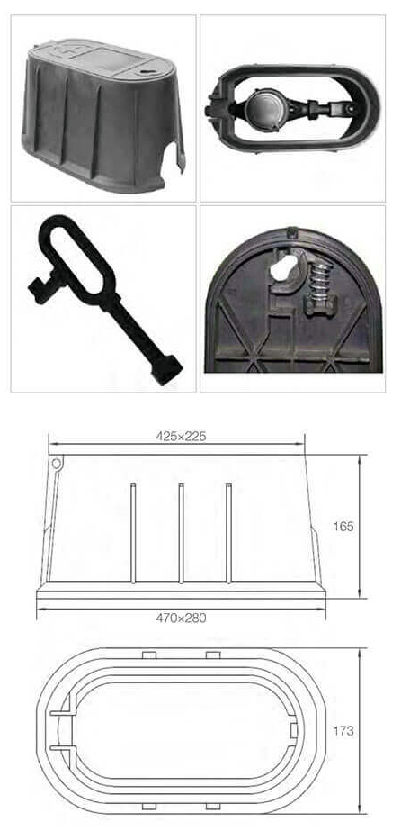
| Name | Upper | Bottom | Height | Weight |
| mm | mm | mm | KGS | |
| Water meter box | 470*280 | 425-225 | 165 | 2.5 |
| Name | Length | Width | Height |
| mm | mm | mm | |
| Water meter box | 313 | 189 | 176 |
- Oil & Gas Sector
- Chemical Industry
- Pharmaceutical Industry
- Water Treatment Industry
- Paper Pulp industry
- Fertilizer Industry
- Food Processing Companies
- Engineering Works
- Fabricators
- Shipbuilding & Marine
- Steam & Power Generation
- Refrigeration & Air Conditioning
